Product Feature:
Compatibility: The product is suitable for use in bell-type and type transmissions, as well as other applications.
High-Speed Cutting: The product is designed to meet the needs of high-speed cutting, implying that it can operate at high speeds while maintaining accuracy and precision.
Direct Mounting: The product can be directly mounted onto the main shaft for cutting, making it easy to install and use.
Fast Knife Change: The product has a super-fast knife change capability, allowing for knife-to-knife exchange within one second. This helps to reduce downtime and increase productivity.
Improved Detection: The machine can be detected by the position of the upper and lower loosening of the clamping tool, which improves the accuracy and speed of the mechanical tool change. This feature helps to ensure that the tool is correctly positioned and secured, which is essential for maintaining accuracy and precision during cutting.
Overall, the product appears to be designed for high-speed cutting applications and includes features such as fast knife change and improved detection to increase productivity and accuracy. The fact that it can be directly mounted onto the main shaft for cutting also makes it a convenient and user-friendly tool.
Working Feature:
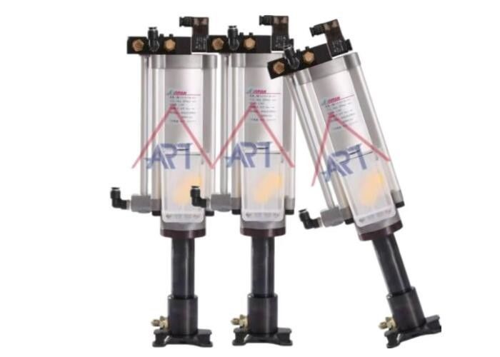
1.Specially designed for vertical and built-in spindles, the cylinder provides hydraulic power and can be used with hydraulic pressure.

2.The modular design includes control valves with wall-mounted connections, as well as hidden pneumatic and hydraulic lines, which not only improve gas flow but also make the appearance more concise and attractive, while saving installation time and reducing the cost of joint air pipes.
What cause hydraulic cylinder leak?
Certainly! Hydraulic cylinder leaks can occur due to a variety of reasons:
Natural Wear and Tear: Seals, which are crucial for maintaining a tight seal within the cylinder, naturally degrade over time due to constant exposure to hydraulic fluid, pressure changes, and friction. When these seals wear out, they lose their ability to contain the fluid effectively, resulting in leaks.
Mechanical Damage: The cylinder rod, which moves back and forth within the cylinder, can sustain scratches or other forms of damage. These imperfections compromise the integrity of the seals, allowing hydraulic fluid to bypass them and leak out.
Contamination: Presence of contaminants such as dirt, debris, or particles within the hydraulic fluid can cause abrasion or damage to the seals. This compromises their ability to maintain a tight seal, leading to leaks.
Excessive Pressure: If the hydraulic system experiences pressure levels beyond its designed capacity, it can cause seals to fail or hydraulic lines to rupture, resulting in leaks.
Installation Errors: Incorrect installation of seals or other components can create gaps or misalignments, allowing fluid to leak. Adhering to manufacturer guidelines and employing proper installation techniques is crucial to prevent such leaks.
Corrosion: Over time, exposure to corrosive elements or contaminated hydraulic fluid can lead to corrosion within the system. Corrosion damages seals and other components, eventually causing leaks.
Temperature Effects: Extreme temperatures can affect the properties of hydraulic fluid and the flexibility of seals. High temperatures can accelerate seal degradation, while low temperatures can cause seals to harden and lose their effectiveness, both leading to potential leaks.
General Wear and Aging: Like any mechanical system, hydraulic cylinders experience wear and aging over time. Components such as seals, piston rods, and cylinder walls gradually wear out, increasing the likelihood of leaks. Regular maintenance and inspection are essential to identify and address these issues before they escalate into leaks.
To mitigate hydraulic cylinder leaks, proactive measures such as routine inspection, timely replacement of worn components, use of quality hydraulic fluid, and adherence to proper installation and operating practices are essential.
Order Form
BMV--10--U--16--M--70--MA
1) 2) 3) 4) 5) 6)
| BMV:Supercharged knife punch pneumatic cylinder |
| 1) |
Diameter |
10:Ø100 12:Ø125 |
| 2) |
Applicable model |
U:used to MC |
| 3) |
Oil pressure ratio |
11=11:1 12=12:1 16=16:1 25=25:1 30=30:1 39=39:1 51=51:1 |
| 4) |
|
M:With hydraulic detection device
N:No hydraulic detection device
|
| 5) |
Spit volume |
50cc, 70cc, 110cc, 150cc,etc |
| 6) |
Mounting type |
FA:vertical type,LB:horizontal type |
Product Description
1.Working pressure: The pump can operate within a pressure range of 0.4 megapascals (MPa) to 0.6 MPa. This can also be expressed as 4 kilograms-force per square centimeter (kgf/cm²) to 6 kgf/cm². The compressed air used to filter the pump should also be within this pressure range.
2.Transmission oil: The pump is designed to work with a specific viscosity grade of oil, which is ISO VG32 or an equivalent viscosity grade.
Working temperature: The pump can operate within a temperature range of 0 degrees Celsius to 60 degrees Celsius.
Split out quantity: The pump can output four different quantities of oil, which are 150cc, 110cc, 70cc, and 50cc.
Voltage: The pump can operate with three different voltage levels, which are DC24, AC110, and AC220.
Suitable for direct drive spindle, motor built-in spindle, etc., special for high-speed cutting:
The hydraulic motor or spindle is designed to be used in direct drive applications, such as motor built-in spindles.
The motor or spindle is specifically designed for high-speed cutting, indicating that it is capable of operating at high speeds while maintaining its performance and reliability.
FAQ
Q1: We have our own factory and can provide the best price and service.
Q2: We accept customization or non-standard products.
Q3: The MOQ depends on the customer's needs, and trial orders are welcome before mass production.
Q4: The delivery time is 7 days if the company has stock, and 15-30 working days if we don't have stock. However, the delivery time also depends on the quantity and requirements of the products.
Q5: The company's payment terms are T/T.
Q6: The company does not provide samples.
The hydraulic cylinder working principal
Hydraulic cylinders operate based on the principles of fluid mechanics and Pascal's law, which states that pressure applied to a confined fluid is transmitted equally in all directions. Here's a detailed explanation of the working theory of hydraulic cylinders:
Basic Components
- Cylinder Barrel: The main body of the cylinder that houses the piston and the hydraulic fluid.
- Piston: A solid cylinder that moves back and forth inside the barrel.
- Piston Rod: Attached to the piston, it extends out of the cylinder to transmit the generated force to the load.
- End Caps: The ends of the cylinder, one typically containing ports for fluid entry and exit.
- Seals: Prevent fluid leakage and maintain pressure within the cylinder.
- Hydraulic Fluid: Incompressible fluid (usually oil) that transmits the applied pressure.
Operating Principles
1. Hydraulic System Setup
- A hydraulic pump generates flow and pressure in the hydraulic fluid.
- Hydraulic fluid is directed into the cylinder through a series of valves and hoses.
2. Fluid Power Transmission
- When hydraulic fluid is pumped into the cylinder via the input port, it exerts pressure on the piston.
- According to Pascal's law, this pressure is transmitted equally in all directions within the cylinder.
3. Piston Movement
- The pressure of the hydraulic fluid forces the piston to move. If the fluid is pumped into the bottom side of the piston (piston side), the piston rod extends (outward movement).
- Conversely, if fluid is directed to the rod side (top side of the piston), the piston retracts (inward movement).
4. Force Generation
- The force exerted by the piston is a product of the hydraulic pressure and the surface area of the piston
-
- 5. Control Mechanisms
- Valves: Control the direction, pressure, and flow rate of the hydraulic fluid. Directional control valves determine whether the piston extends or retracts.
- Flow Control Valves: Regulate the speed of the piston by controlling the rate of fluid flow into the cylinder.
- Pressure Relief Valves: Protect the system from excessive pressure by diverting fluid when the pressure exceeds a set limit.
Types of Hydraulic Cylinders
1. Single-Acting Cylinders
- Fluid pressure is applied to only one side of the piston, causing movement in one direction.
- A return mechanism (spring or external force) is used to move the piston back when the pressure is released.
2. Double-Acting Cylinders
- Fluid pressure can be applied to both sides of the piston, allowing for controlled movement in both directions.
- More versatile and commonly used in various applications.
Applications
Hydraulic cylinders are widely used in applications requiring substantial force and precise control, such as:
- Construction Equipment: Excavators, loaders, cranes.
- Industrial Machinery: Presses, injection molding machines, conveyor systems.
- Automotive Systems: Brakes, suspension systems.
- Aerospace: Landing gear, flight control actuators.
Example: Extension and Retraction Cycle
-
Extension:
- Hydraulic fluid is pumped into the cylinder on the piston side.
- The increasing pressure forces the piston rod to extend, pushing the load.
-
Retraction:
- The directional valve switches, allowing hydraulic fluid to flow into the rod side of the cylinder.
- The pressure on the rod side forces the piston to retract, pulling the load.
Conclusion
The working theory of hydraulic cylinders revolves around using hydraulic fluid to transmit force and motion. By exploiting the principles of fluid mechanics and Pascal's law, hydraulic cylinders can generate significant force and perform various tasks in industrial, automotive, construction, and aerospace applications. The precise control over pressure and flow makes hydraulic systems highly efficient and versatile for numerous mechanical operations

 Your message must be between 20-3,000 characters!