Product Feature:
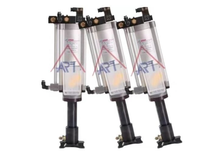
Air oil unclamping booster pneumatic cylinder with a diameter of 12 mm and a ø125 pressure boosting ratio of either 11:1 or 30:1.
The purpose of this type of cylinder is to provide a more powerful and precise clamping force for industrial applications. The booster works by using compressed air to pump oil at a higher pressure than what the input air pressure would normally allow, thus amplifying the force output of the cylinder.
The diameter of 12 mm refers to the size of the cylinder's bore, which determines the maximum force output that the cylinder can generate. The pressure boosting ratio of ø125 could mean that the cylinder's output pressure is either 11 times or 30 times greater than the input air pressure, depending on the specific model.
Overall, this type of pneumatic cylinder is designed for applications that require high clamping force and precision, such as in the manufacturing of automotive parts or in the assembly of aerospace components. The air oil unclamping booster technology allows for a more efficient and powerful clamping force, which can improve production efficiency and quality control.
Order Form
BMV--10--U--16--M--70--MA
1) 2) 3) 4) 5) 6)
| BMV:Supercharged knife punch pneumatic cylinder |
| 1) |
Diameter |
10:Ø100 12:Ø125 |
| 2) |
Applicable model |
U:used to MC |
| 3) |
Oil pressure ratio |
11=11:1 12=12:1 16=16:1 25=25:1 30=30:1 39=39:1 51=51:1 |
| 4) |
|
M:With hydraulic detection device
N:No hydraulic detection device
|
| 5) |
Spit volume |
50cc, 70cc, 110cc, 150cc,etc |
| 6) |
Mounting type |
FA:vertical type,LB:horizontal type |
Product Description
1.Working pressure: The pump can operate within a pressure range of 0.4 megapascals (MPa) to 0.6 MPa. This can also be expressed as 4 kilograms-force per square centimeter (kgf/cm²) to 6 kgf/cm². The compressed air used to filter the pump should also be within this pressure range.
2.Transmission oil: The pump is designed to work with a specific viscosity grade of oil, which is ISO VG32 or an equivalent viscosity grade.
Working temperature: The pump can operate within a temperature range of 0 degrees Celsius to 60 degrees Celsius.
Split out quantity: The pump can output four different quantities of oil, which are 150cc, 110cc, 70cc, and 50cc.
Voltage: The pump can operate with three different voltage levels, which are DC24, AC110, and AC220.
Suitable for direct drive spindle, motor built-in spindle, etc., special for high-speed cutting:
The hydraulic motor or spindle is designed to be used in direct drive applications, such as motor built-in spindles.
The motor or spindle is specifically designed for high-speed cutting, indicating that it is capable of operating at high speeds while maintaining its performance and reliability.
Hydraulic cylinders can leak for several reasons, including:
Worn seals: Seals can degrade over time due to friction, pressure, and exposure to hydraulic fluid. Once seals wear out, they may fail to properly contain the hydraulic fluid, leading to leaks.
Scratches or damage to the cylinder rod: If the rod inside the cylinder is scratched or damaged, it can compromise the integrity of the seals, allowing hydraulic fluid to leak past them.
Contaminants: Dirt, debris, or other contaminants in the hydraulic fluid can cause damage to seals or other components of the hydraulic system, leading to leaks.
Over pressurization: Excessive pressure within the hydraulic system can cause seals to fail or hydraulic lines to rupture, resulting in leaks.
Improper installation: Incorrect installation of seals or other components can result in leaks. It's important to follow manufacturer guidelines and use appropriate tools and techniques during installation.
Corrosion: Corrosion can occur within the hydraulic system, leading to damage to seals or other components and ultimately resulting in leaks.
Temperature extremes: Extreme temperatures can affect the viscosity of the hydraulic fluid and the flexibility of seals, potentially leading to leaks.
Age and wear: Over time, the various components of a hydraulic cylinder can wear out, leading to leaks. Regular maintenance and inspection can help identify and address issues before they result in leaks.
To prevent hydraulic cylinder leaks, it's important to regularly inspect the system for signs of wear or damage, replace worn seals and components, use high-quality hydraulic fluid, and maintain proper operating conditions.
Flow Control Valves in Hydraulics

Flow control valves are essential components in hydraulic systems, used to regulate the flow rate of hydraulic fluid. By controlling the flow rate, these valves help manage the speed and response of hydraulic actuators, ensuring precise and efficient operation of the system. Here's an overview of flow control valves in hydraulics:
Types of Flow Control Valves
-
Throttle Valves:
Simple, adjustable orifices that control flow by varying the size of the opening through which the hydraulic fluid passes.Example: Needle valves.
-
Pressure Compensated Flow Control Valves:
Maintain a consistent flow rate despite changes in pressure in the hydraulic system.Have a built-in mechanism to adjust the flow rate in response to pressure variations.
-
Non-Pressure Compensated Flow Control Valves:
The flow rate varies with pressure changes.Less complex and less expensive but require more manual adjustment to maintain desired flow rates.
-
Flow Dividers:
Distribute the flow of hydraulic fluid equally or proportionally between two or more circuits.Ensure synchronized movement of multiple actuators.
-
Priority Flow Control Valves:
Provide a constant flow rate to a primary circuit while supplying excess flow to a secondary circuit.Ensure that critical functions receive priority flow.
Components of Flow Control Valves
-
Orifice:
An opening whose size can be adjusted to control the flow rate.Determines the resistance to flow, thereby regulating the speed of actuators.
-
Spool:
A movable component within the valve body that adjusts the orifice size.Can be manually or automatically adjusted.
-
Pressure Compensator:
A mechanism that automatically adjusts the flow rate to compensate for pressure variations.Ensures consistent performance under varying loads.
-
Bypass Check Valve:
Allows free flow of fluid in one direction and controlled flow in the opposite direction.Commonly used in conjunction with flow control valves to permit unrestricted return flow.
Applications of Flow Control Valves
-
Speed Control of Hydraulic Cylinders and Motors:
Regulate the extension and retraction speed of hydraulic cylinders.Control the rotational speed of hydraulic motors.
-
Synchronization of Multiple Actuators:
Ensure coordinated movement in applications with multiple hydraulic cylinders or motors.
-
Pressure and Flow Prioritization:
Allocate flow to priority functions while allowing secondary functions to operate with remaining flow.
-
Flow Division and Combining:
Divide the flow evenly or proportionally between different circuits. Combine flow from multiple sources into a single flow stream.
Installation and Maintenance
-
Proper Sizing:
Select flow control valves based on the maximum flow rate and pressure of the hydraulic system.Ensure compatibility with the fluid type and operating conditions.
-
Correct Placement:
Install flow control valves in appropriate locations to achieve desired control.Consider the flow direction and pressure requirements.
-
Regular Inspection and Maintenance:
Check for signs of wear, leakage, and blockage.Clean or replace components as needed to maintain optimal performance.
-
Adjustment and Calibration:
Fine-tune the valve settings to achieve precise control.Recalibrate pressure-compensated valves to account for system changes.
Flow control valves play a crucial role in optimizing the performance and efficiency of hydraulic systems. Proper selection, installation, and maintenance are key to ensuring reliable and precise flow regulation.
Applications:
Air oil unclamping booster pneumatic cylinders can be used in a variety of industries that require high clamping force and precision.
Here are a few examples:
1.Automotive manufacturing: In the production of automotive parts, air oil unclamping booster cylinders can be used to clamp and hold components in place during machining or assembly processes. This ensures that the parts remain securely in place and are properly aligned, resulting in higher quality and more reliable products.
2.Aerospace manufacturing: In the assembly of aerospace components, air oil unclamping booster cylinders can be used to hold large and heavy parts in place while they are being machined or assembled. The high clamping force and precision of these cylinders ensure that the parts remain securely in place and are not damaged during the manufacturing process.
3.Medical device manufacturing: In the production of medical devices, air oil unclamping booster cylinders can be used to hold small and delicate components in place during machining or assembly processes. The high precision of these cylinders ensures that the parts are not damaged or deformed during the manufacturing process, resulting in higher quality and more reliable products.
4.Machine tool manufacturing: In the production of machine tools, air oil unclamping booster cylinders can be used to provide high clamping force and precision for holding workpieces in place during machining processes. This can improve the accuracy and efficiency of the machining process, resulting in higher quality and more precise products.
Overall, air oil unclamping booster pneumatic cylinders can be used in any industry that requires high clamping force and precision, and where the cost of downtime or product failure is high.
Can hydraulic cylinder be rebuilt?
Hydraulic cylinders can be rebuilt. Rebuilding a hydraulic cylinder involves disassembling the cylinder, inspecting its components for wear or damage, replacing any damaged parts such as seals, O-rings, rods, or pistons, and then reassembling the cylinder with the new parts.
Here's a general overview of the steps involved in rebuilding a hydraulic cylinder:
-
Disassembly: The cylinder is removed from its housing and disassembled carefully, taking note of the arrangement of parts and any specific configurations.
-
Inspection: Each component of the cylinder is inspected for signs of wear, damage, or corrosion. This includes the piston, rod, seals, O-rings, gland, and housing.
-
Replacement of Parts: Any worn or damaged parts are replaced with new ones. This typically includes seals, O-rings, and possibly other components depending on the extent of wear.
-
Cleaning: All components, including the housing, are thoroughly cleaned to remove any dirt, debris, or old lubricants.
-
Reassembly: The cylinder is reassembled, ensuring that all parts are properly aligned and seated. Care must be taken to avoid damaging any seals during reassembly.
-
Testing: Once reassembled, the cylinder is tested for proper operation. This may involve pressurizing the cylinder to check for leaks, ensuring smooth movement of the piston and rod, and verifying that all functions operate as expected.
-
Installation: Once the cylinder passes testing, it can be reinstalled in its original application.
Rebuilding a hydraulic cylinder can extend its service life and is often a cost-effective alternative to purchasing a new cylinder, especially for larger or custom cylinders where replacements may be more expensive or difficult to find. However, it requires knowledge of hydraulic systems and proper maintenance techniques to ensure the rebuilt cylinder performs reliably.
FAQ
Q1: We have our own factory and can provide the best price and service.
Q2: We accept customization or non-standard products.
Q3: The MOQ depends on the customer's needs, and trial orders are welcome before mass production.
Q4: The delivery time is 7 days if the company has stock, and 15-30 working days if we don't have stock. However, the delivery time also depends on the quantity and requirements of the products.
Q5: The company's payment terms are T/T.
Q6: The company does not provide samples.
What is the export standard for hydraulic cylinder?
The export standards for hydraulic cylinders encompass various international and regional regulations, guidelines, and specifications to ensure safety, reliability, and performance. These standards are set by different organizations and can vary based on the destination country or industry. Here are some key aspects and common standards that hydraulic cylinders must adhere to for export:
Quality and Performance Standards:
Ensure the hydraulic cylinder performs reliably under specified conditions.
Include tests for pressure, load capacity, and cycle life.
Safety Standards:
Ensure the hydraulic cylinder is safe to use in its intended application.
Address potential risks like leaks, bursts, and failure under load.
Material and Manufacturing Standards:
Specify the types of materials used for components to ensure durability and strength.
Include manufacturing processes and quality control measures.
Environmental and Compliance Standards:
Address environmental impact, including the use of eco-friendly materials and processes.
Ensure compliance with local regulations in the export destination.
Common Standards and Regulations
ISO Standards (International Organization for Standardization):
ISO 6020/2: Hydraulic fluid power—Mounting dimensions for single rod cylinders, 16 MPa (160 bar) series.
ISO 6022: Hydraulic fluid power—Mounting dimensions for single rod cylinders, 25 MPa (250 bar) series.
ISO 10100: Hydraulic fluid power—Acceptance tests for hydraulic cylinders.
DIN Standards (German Institute for Standardization):
DIN 24554: Hydraulic fluid power—Cylinders—Mounting dimensions of rod end with male thread.
DIN ISO 3320: Hydraulic fluid power—Cylinders—Standard metric series.
NFPA Standards (National Fluid Power Association, USA):
NFPA T3.6.7 R2-2009: Hydraulic fluid power—Cylinders—Port dimension, mounting, and other geometrical data.
NFPA/T3.6.39: Hydraulic fluid power—Cylinders—Vocabulary.
JIS Standards (Japanese Industrial Standards):
JIS B 8354: Hydraulic cylinders—General rules for testing and inspection.
JIS B 8367: Hydraulic cylinders—Single rod, double acting cylinders.
CE Marking (Conformité Européenne):
Required for products sold within the European Economic Area (EEA).
Ensures compliance with EU safety, health, and environmental protection requirements.
RoHS (Restriction of Hazardous Substances):
Ensures that hydraulic cylinders comply with regulations limiting hazardous substances, particularly for products entering the EU market.
Documentation and Certification
To meet export standards, hydraulic cylinder manufacturers typically need to provide the following documentation and certifications:
Product Specifications and Technical Data Sheets:
Detailed information about the cylinder’s design, materials, dimensions, and performance characteristics.
Test Reports and Certificates:
Evidence that the product has been tested and meets relevant standards, such as pressure tests, fatigue tests, and material tests.
Quality Management System Certification:
Certification such as ISO 9001, indicating the manufacturer follows internationally recognized quality management practices.
Compliance Declarations:
Statements confirming that the product complies with relevant regulations, such as CE marking for Europe.
Material Safety Data Sheets (MSDS):
Information on the materials used in the hydraulic cylinder, particularly for compliance with environmental and safety regulations.
Conclusion
Ensuring that hydraulic cylinders meet export standards involves adherence to various international and regional regulations that cover quality, safety, materials, and environmental impact. Manufacturers need to provide thorough documentation and obtain necessary certifications to demonstrate compliance with these standards. By doing so, they can ensure their products are accepted in global markets and perform reliably and safely in their intended applications.

 Your message must be between 20-3,000 characters!